 Lithium-ion & Polymer Battery Packs Manufacturer | KBT Battery


Company Blog
High quality high performance excellent service
Search productSearch post
High quality high performance excellent service
A battery can pass a capacity test and still fail inside the customer’s equipment. It may shut down when a motor starts, heat at the connector, refuse to charge, or work on the bench but fail after vibration and moisture exposure.
These are not always cell problems. When buyers investigate why battery packs fail, the cause is often cable size, connector selection, pinout, charger compatibility or BMS settings. This guide helps teams turn symptoms into specifications before sample approval.
The pack, equipment and charger operate as one system. A weak connection adds resistance; startup current creates voltage sag; the BMS disconnects the output. The customer then reports a “dead battery,” although the cells may still hold energy.
| Field symptom | Possible integration cause | What to check first |
|---|---|---|
| Device resets under load | Cable voltage drop or undersized connector | Loaded voltage at pack and device terminals |
| Pack shuts off at motor start | BMS current threshold below surge demand | Startup-current waveform and protection setting |
| Connector becomes hot | High contact resistance or poor crimp | Terminal, crimp pull test and temperature rise |
| Battery will not charge | Wrong charger, polarity or charge-port wiring | Chemistry, charge voltage, pinout and port design |
| Runtime varies between units | Cell imbalance, harness loss or inconsistent load | Cell-group voltage and current under the same test |
| Outdoor failures appear later | Moisture ingress or cable strain | Seal, wire exit, corrosion and flex points |
Wire gauge must be selected for current, length, allowable temperature rise and voltage drop; capacity in amp-hours does not answer that question. Heat follows P = I^2 x R, so a cable acceptable at average current can become the limiting component during acceleration, radio transmission, pump startup or tool stall.
Ask for:
A production lead longer than the prototype adds resistance. Changing cable length without repeating the loaded test can reduce device voltage and trigger an early BMS cutoff.
Treat cable length as a controlled drawing dimension. Test the final harness, connector and battery together at peak load rather than validating the bare pack with short laboratory leads.
The conductor may be correctly sized while the termination is not. Loose strands, a poor crimp, solder wicking or insufficient strain relief can create a hot spot. Define the terminal and crimp method, then use visual, pull-force and loaded temperature checks where appropriate. Preserve returned connectors for analysis.
Connector selection is not only about whether two plugs mate. Current rating, contact resistance, locking, mating cycles, vibration, polarization, ingress exposure and available installation space all affect performance.
Common battery connector problems include:
KBT’s outdoor battery packs with DC5521 connectors illustrate why a connector must be evaluated as part of a defined model. The listed voltage, capacity and discharge current differ by configuration; “DC5521” alone does not establish compatibility.
Two identical housings can have different pin assignments. Even familiar DC barrel connectors should not be assumed to use the same polarity. A replacement pack can therefore be electrically wrong while appearing mechanically correct.
Put the connector manufacturer, series, mating part, pin numbering and polarity on the drawing. For multi-pin plugs, identify power, ground, temperature-sensor and communication pins. Use a keyed design when reverse mating is a foreseeable risk.
Motors, compressors, heaters and large input capacitors can draw a brief current much higher than steady operation. If the BMS overcurrent threshold or delay is too low, the pack disconnects. Selecting a protection board only from the load’s printed wattage is therefore risky.
A proper review separates:
Texas Instruments describes protection functions for overvoltage, undervoltage, discharge overcurrent and short circuit. The device and settings must match the pack and load; “BMS included” is not a complete specification.
A genuine battery BMS failure is possible, but many reported failures are specification mismatches. Cell chemistry, series count, allowable charge voltage, discharge cutoff and temperature limits must agree with both the cells and charger.
Changing cell count changes the required protection architecture. A charger for another chemistry can reach the wrong endpoint. The BMS is not a substitute for a matched charger.
Record the nominal and maximum charge voltage, charge current, BMS thresholds, balancing approach where applicable, and required fault recovery behavior. Validate them on the final sample.
Room-temperature bench testing does not reproduce a hot enclosure, cold morning, wet deck or vibrating vehicle. Moisture corrodes contacts, while repeated flexing can fatigue a wire at the pack exit.
“Waterproof” also needs a defined project requirement. The enclosure, seams, cable gland, connector and mating condition all matter. Do not infer an IP rating unless the exact product has supporting test evidence.
Before sample approval, run tests on the complete power path:
Define the acceptance method so later batches can be checked against the same limits.
KBT supports standard packs and project-specific evaluation across its lithium battery pack range. To review the cable, connector and BMS as one system, send:
KBT can evaluate these pack elements. Document availability and testing must be confirmed for the exact model and market.
Yes. Cable resistance can cause voltage drop under load. The BMS or device may then reach its undervoltage threshold even when the cells retain charge. Measure voltage at both ends of the harness during peak current.
Bench loads may not reproduce motor startup, long cables, connector resistance, vibration or enclosure temperature. Test the production-intent battery, harness, charger and equipment together using the real duty cycle.
No. The cells, wiring, connector, fuse, charger and equipment must all support the load. Raising a protection threshold without engineering review can remove a safeguard while leaving the actual problem unresolved.
Request the agreed specification, drawings, model-specific test records and applicable transport documents. The U.S. PHMSA states that lithium battery designs offered for transportation must pass UN 38.3 design tests and that test summaries must be available in the supply chain. Confirm requirements for the specific battery and shipping route.
Understanding why battery packs fail requires looking beyond the cells. Cable resistance, termination quality, connector fit, polarity, current transients, BMS thresholds, charger matching and the operating environment should be reviewed as one system.
For a standard or OEM pack review, send KBT an inquiry with your application, voltage range, load-current profile, runtime, dimensions, connector photo, expected quantity, target market and compliance needs. That information is far more useful than a request for “a 12V battery” and helps expose integration risks before production.
The short answer is sometimes, but matching the "12V" label is not enough. A pack can fit the compartment and still be wrong for the motor surge, charger, connector or wet environment. So, can a lithium battery replace lead-acid in your product wi...
View details
Learn how to specify a custom lithium battery pack for OEM projects, including voltage, capacity, BMS, connectors, cell type, UN38.3, MSDS, UL and CE.
View details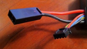
Learn how to specify a custom lithium battery pack with cable and connector. Use this buyer checklist and contact KBT for an OEM quote.
View detailsTags: OEM battery sourcing, custom lithium battery packs, battery procurement, cylindrical cells Total body word count: 1,537 Reading time: 8 minutes Choosing an OEM battery manufacturer is a product-risk decision, not simply a search for ...
View details